Professional electrical drawing software for schematics and wiring diagrams. Design multi-page drawings, manage cables and terminals, lay out the control panel to scale, and auto-generate Bills of Materials, with nothing to install.
Everything you need from single-line diagrams to full industrial multi-sheet portfolios.
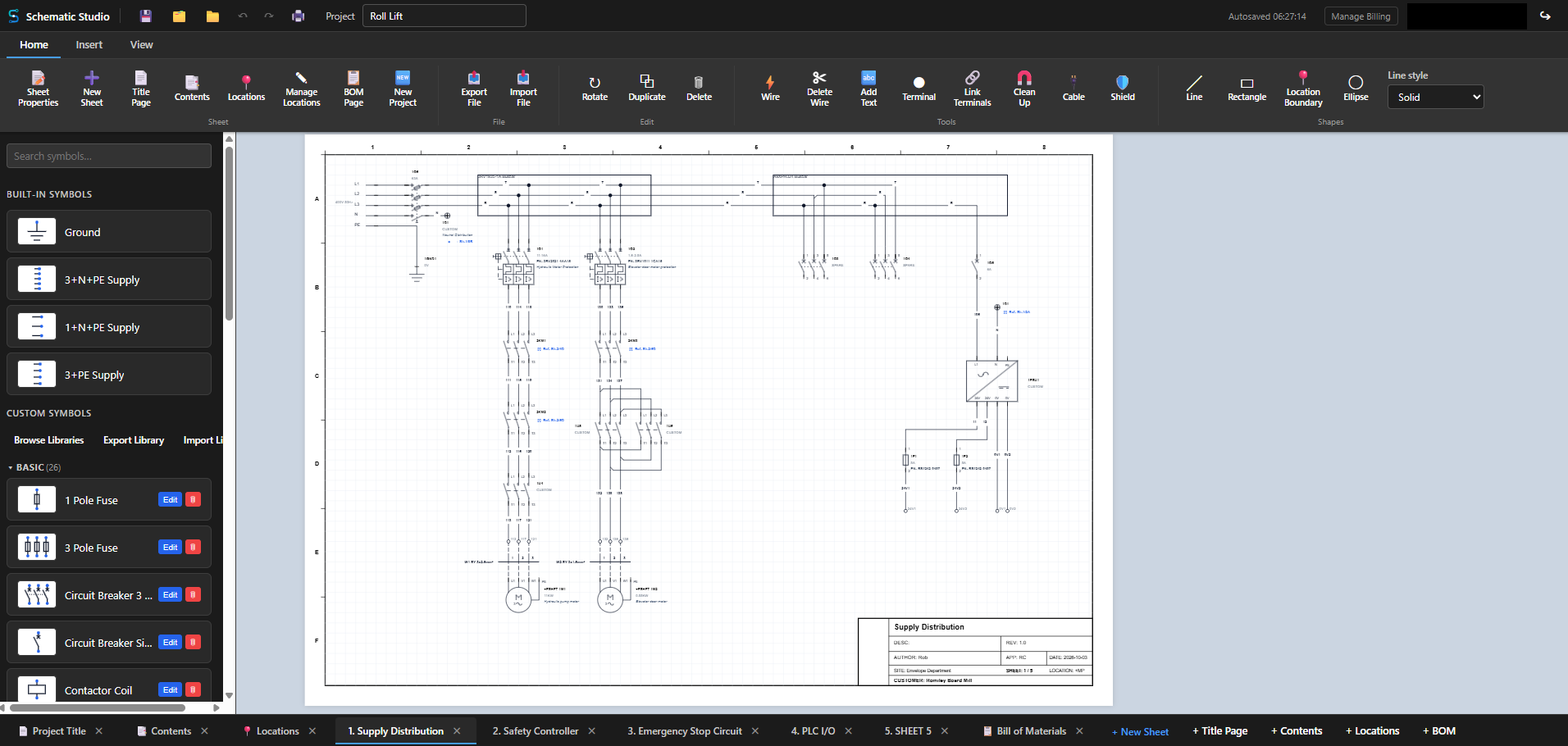
Route wires seamlessly with magnet-assisted wire cleanup, net labeling, and automatic net numbering across components. Numbers count up along each conductor and stay with their wire when you move or rebuild a circuit.
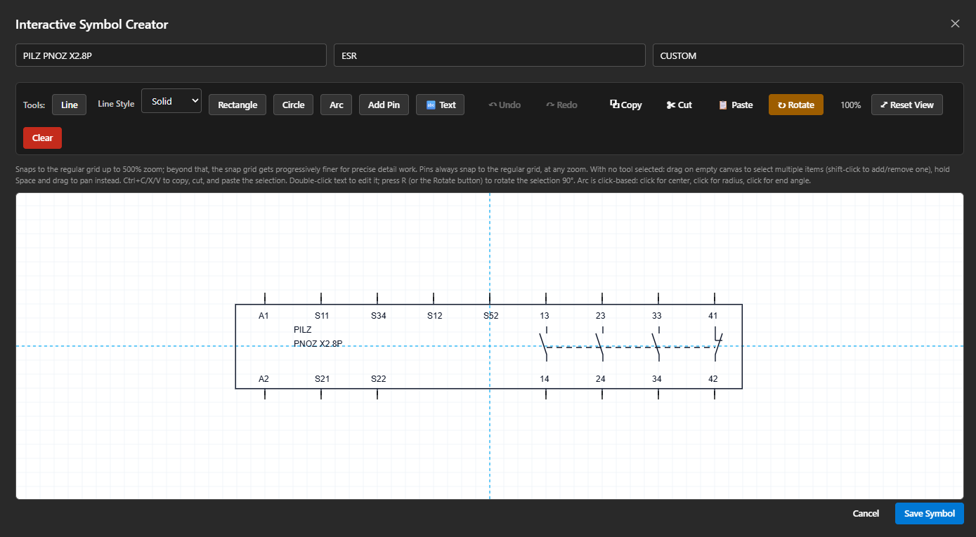
Create detailed electrical components using precise drawing tools, custom pin placements, and grid snapping that switches off when you zoom in for fine detail.
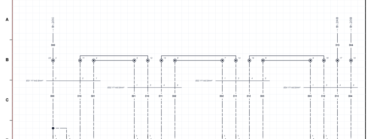
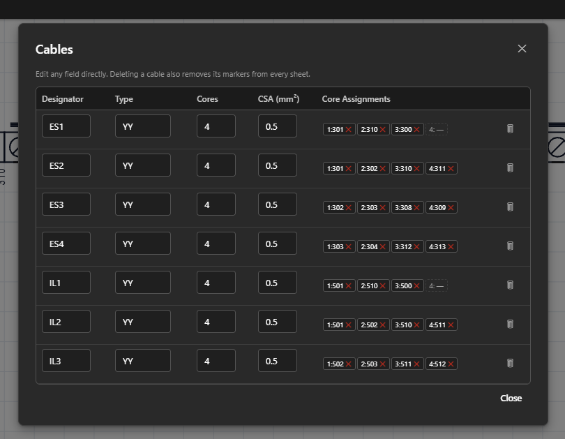
Bundle individual wire runs into structured cables. Define CSA specifications, core counts, and core assignments with ease. Colour-code every core (BRN, BLK, GRY, BLU and more) or show core numbers.
Track wires across multi-page projects automatically with dynamic target sheet references.
Generate real-time Bills of Materials grouped by designator, model number, and sheet location. Export to CSV in one click.
Organize designs with automated Title Pages, dynamic Contents sheets, and standardized title block frames (A2, A3, A4).
Import ready-made symbol libraries in one click, then add to them or amend your own copy. The originals are never touched. Export your own libraries to reuse or share.
Build PLC modules from their make, model, inputs, outputs and supply connections, each with an address and a function. Wire references show which PLC channel a wire goes to, on other sheets or on the same one.
Every PLC input and output in one table: address, type, function, the wire connected to it and the device it goes to. Spares are listed too. Save it as a CSV, print it, or add it to the drawing set as a page that updates as you draw.
Drop a control relay (CR), relay (K) or motor contactor (KM) coil, in rectangle or round style, then give it contacts: its own plus auxiliary blocks, with their terminal numbers. Built-in child N.O, N.C and 3-pole power contacts pick up those numbers from the parent wherever they sit in the drawing.
Right-click a part and swap it for another symbol. The designator, position and links stay, the wires stay attached, and every wire keeps its number, so changing a breaker or contactor never means renumbering the circuit.
Set a location per sheet, override it per component, or draw a boundary box to assign a whole region at once. Designators show the +CP prefix wherever it differs, and a dynamic Locations page lists where each is used.
Define a cable once, with its type, core count, CSA and core colours, then pick it whenever you bundle wires. Start from a standard colour set and save your library to a file to reuse in other projects.
Import DXF drawings or STEP models of your backplate and components and arrange them to scale. Clip parts onto DIN rails, add trunking, and measure the gaps with dimensions that follow the parts as you move them. Turn the panel round in 3D to check depth and clearances. Every part stays linked to its schematic component and the BOM.
Issue revisions with a date, description and author, choose the sheets each one covers, and see what has changed since the last. Title blocks show the current revision with a revision table above them.

Short clips, straight from the editor: draw, number, cable, lay out and list your parts without leaving the browser.
Route wires seamlessly with magnet-assisted wire cleanup, net labeling, and automatic net numbering across components. Everything snaps to the grid, and you choose how junctions are drawn: a classic dot, or a neat angled junction in the wire itself.
Draw your wires and SchematicStudio numbers them as you go. Wire numbers follow the net across the drawing and renumber themselves, so there is nothing to type and nothing to keep in step by hand.
Place terminals straight onto the wires of your schematic. Choose standard or PE, pick the terminal block and its model, set the position and decide how the location is labelled. Every terminal flows through to the panel layout, ready to drop onto a DIN rail.
Bundle individual wire runs into structured cables. Define CSA specifications, core counts, and core assignments with ease, and see every cable's cores in one window.
Track wires across multi-page projects automatically. Dynamic target sheet references show where each connection continues, and keep up as your project changes.
Terminals, wire numbers, cable cores and cross-sheet references are drawn on the sheet for you and stay in step with your cable schedule, so the drawings you print are ready for the panel shop.
Box up a finished circuit, save it to your own library and drop it into any project. Parts renumber automatically when you place it, so a proven motor starter or control block takes seconds, not an afternoon.
Generate a real-time Bill of Materials grouped by designator, model number, and sheet location. Export to CSV in one click.
Start free. Every new account also gets 30 days of full Pro access, no card required.
For single-sheet jobs and getting started
For full projects and ongoing work
Includes a 30-day free trial
Symbols, reports, panel layout and revisions, all in the same project.
Build reusable custom components directly within the application. Add custom terminals, geometry, rotational handles, and text attributes. Draw to a clean grid, then zoom in up to 1500%, where snapping switches off for fine detail. Save every symbol into a library of your choice to keep things organised.
Try the Studio
Automatically scan placed terminal markers across your entire project to assemble terminal strip blocks instantly. Keep track of complex net topology with real-time wire cross-referencing tables, and produce a PLC I/O schedule listing every input and output with its function, wire and destination.
Explore Reports
Take the schematic into the panel. Import DXF drawings or STEP models of your backplate and components, place each schematic part on the plate, and clip terminal strips and devices onto DIN rails. A STEP file gives you the 2D footprint, the depth and the DIN rail position in one go, and a 3D view shows the whole panel with the real component shapes, so you can spot depth problems before you build. Add trunking, check for overlaps, and drop dimension lines that follow the parts when you move them. Each placed part shows its designator and schematic reference, and the BOM records what has been placed.
Try Panel LayoutIssue Rev A, B, C as the job moves on, with a date, a description and who made the change. Pick the sheets each revision covers, or let the editor point out the ones that have changed since the last. Every sheet's title block shows its current revision, and the latest revisions are listed in a table above it.
Start DrawingSchematicStudio is online electrical CAD for people who produce electrical drawings: panel builders, machine builders, controls engineers, electricians and maintenance teams.
Draw power and control circuits across numbered sheets, with wire numbering, terminal strips and a contents page generated for you.
Group wires into cables, set core counts and sizes, and keep every core assigned. Cross-sheet references show where a wire continues.
Create PLC modules with addressed inputs and outputs and their functions, wire to them like any other component, and produce the PLC I/O schedule as a table, a CSV or a page in the drawing set.
Arrange your parts on the backplate to scale, mount them on DIN rails, add trunking, check the spacing and view the panel in 3D from your STEP models, all linked back to the schematic. From schematic to panel layout.
Keep a revision log for the whole drawing set, with a revision table on every sheet, so everyone can see what changed and when.
Every part on your drawings is counted for you, grouped by designator and model number, and exported to CSV for purchasing.
SchematicStudio is online electrical CAD software. You draw electrical schematics and wiring diagrams in your web browser, across as many sheets as your plan allows, with cable management, terminal blocks, cross-sheet wire references and a live bill of materials.
No. SchematicStudio runs in your browser, so there is nothing to install or update. Your projects are saved to your account and you can open them from any computer.
Yes. The Free plan lets you draw up to 2 schematic sheets per project with smart wiring, a live BOM, title pages, contents sheets and standard A2, A3 and A4 title blocks. Every new account also gets 30 days of full Pro access, with no card required.
Yes. The Symbol Studio lets you draw your own components with custom pins, text and geometry, and keep them in symbol libraries you can import, export and share. Pro plan.
Yes. The PLC Module Creator builds a PLC module from its make, model, inputs, outputs and supply connections, each with an address and a function such as Hydraulic or Pneumatic. Wire references on other sheets can show which PLC channel a wire goes to. Pro plan.
Yes. A Panel Layout sheet lets you import DXF or STEP files of your backplate and components, arrange them to scale, mount parts and terminal strips on DIN rails, add trunking and measure the gaps, then check the result in a 3D view built from the real STEP models. Every placed part stays linked to its schematic component, so it shows the designator and the schematic sheet reference, and the BOM shows what has been placed. Pro plan.
Yes. Issue revisions (A, B, C and so on) with a date, description and author, choose which sheets each one covers, and see which sheets have changed since the last revision. Each title block shows its current revision, with a revision table above it.
Yes. Built-in control relay (CR), relay (K) and motor contactor (KM) coils, in rectangle or round style, are parents: give each its own contacts and auxiliary blocks with their terminal numbers. Then place built-in N.O, N.C or 3-pole power child contacts anywhere in the drawing and assign each one a contact from its parent, which supplies the terminal numbers.
Yes. Right-click a part and choose Swap component, then pick the replacement symbol. The part keeps its designator, position and links, its wires stay attached and every wire keeps its number.
Yes. The PLC I/O schedule lists every input and output of the PLC modules on your sheets with its address, type, function, wire and what the wire goes to, spares included. Save it as a CSV, print it, or add it to the portfolio as a page that stays up to date as you draw.
Yes. Give each core a colour (BRN, BLK, GRY, BLU, GRN, YEL and more) or use a standard set, and save the cable to the cable library so you never have to define the same cable twice. Pro plan.
Yes. The BOM is generated live from your drawing, grouped by designator, model number and sheet location, and exports to CSV in one click.
Free to start, with 30 days of full Pro access on every new account. No card required.